Titlebar
Home FAQ and resources Unit F451 Computer
Fundamentals

Unit F452 Programming
Techniques and logical Methods

Unit F453 Advanced
Computer Theory
Unit F454 Computing
Project


F453 Advanced computer
theory

F453 Tests and challenges

3.3.1 Operating systems
   - Operating systems
   - Interrupts
   - Scheduling
   - Memory management
   - Spooling
   - Main components of a PC
 
3.3.2 Translators
   - Translators
   - Assembly and machine code
   - Assemblers
   - Interpretation v compilation
   - Intermediate code
   - Lexical analysis
   - Syntax analysis
   - Code generation
   - Library routines

3.3.3 Computer architectures
   - Von Neumann architecture
   - FDE cycle
   - Alternative architectures
   - RISC and CISC
 
3.3.4 Data representation
   - Floating point numbers
   - Normalisation
   - Accuracy and range

3.3.5 Data structures
   - Static v dynamic
   - Queues, stacks and trees
   - Binary v serial searching
   - Merging data files
   - Insertion and quicksort

3.3.6 HLL paradigms
   - Programming paradigms
   - Programming terms
   - Understanding OO
   - Diagrams used in OO
   - Declarative programs

3.3.7 Programming techniques
   - Functions and procedures
   - Parameters and variables
   - Stacks
   - BNF and syntax diagrams
   - Reverse Polish
   - Convert Polish and infix

3.3.8 Low level languages
   - Registers
   - Addressing
   - Understanding low-level

3.3.9 Databases
   - Flat v relational
   - 3NF relational databases
   - Keys
   - DBMS
   - SQL


3.3.6 e & f - Diagrams used in OO

Introduction
There are a range of 'standard' diagrams used in object oriented programming. The diagrams are 'standard' because they are part of a general purpose standardised language for Object Oriented programming known as UML (Unified Modelling Language), which can be applied to any OO language. The diagrams used to help describe different aspects of an OO program are part of the tools of UML. Having a standard set of diagrams is very useful. If one person leaves a team another can step in and work out what is going on from the diagrams quickly and easily - they don't have to use some in-house diagrams they've never seen before. If everyone in a team is using the same diagrams, there should also be less room for error in interpreting the information. We will run through some of these diagrams in this section.

Class diagrams
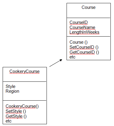
A class diagram shows you the classes in a system. Within each class in the diagram, you can see the name of the class, the data items in that class and the methods used by that class. The overall diagram shows you how the classes are related to each other; they show you which classes inherit data and methods from other classes. Here is an example of a class diagram. You can see two classes, the CookeryCourse class inheriting properties from the Course class. Both classes show you the name of the class, data items in the class and the methods that class has.

ClassDiagram

Object diagrams
An object diagram shows you which real-world objects have been created from a class. Here is an example of an object diagram. You can see that it shows the class Course and the three real courses that have been created from this class, Maths, PE and Music.

ObjectDiagram

Use case diagrams
Use case diagrams depict what happens in a system. It isn’t concerned with how things are done but rather what occurs in the system and how the users interact with it. You can see in this example that customer and the bank are shown outside of a box. This is because they are not part of the system as such, but they do interact with it, passing information and requests for information into and out of the system. When a customer starts a new session, there are a number of options or processes that can occur. These are shown inside the box and are linked to the event we have called ‘a session’.

UseCase

State diagrams
Different things can happen to a real object in its life. Objects can have different ‘states’ or can be in different situations. A state diagram describes these different states, the events which occur that cause an object to change state and the conditions that must be satisfied for the change to be allowed. These diagrams are a good way of summarising the life of objects and all the different things that can happen to them in a system and what triggers those changes. Here is a simple example of a state diagram:

StateDiagram

When talking about state diagrams, we talk about states, events, guards and transitions.

State. A box shows one state that the object can be in. In this example, we have a box for when the book is on the shelf, a box for when the book is lent out and a box for when the book is scrapped and removed from the shelf. A condition during the life of an object in which it satisfies some condition, performs some action, or waits for some event.

Event. An event is when something happens that could cause an object to move from one state to another. In our example, an event is when a borrower requests to borrow a book from the library.

Guard. This is a Boolean expression which, if true, authorises the change of state of an object. In our example, we have a guard set up that checks if the borrower is valid (is their account up to date and have they yet to reach the maximum number of allowable books yet? If their account is valid, and they haven’t reached the maximum number of loans, then the book is allowed to change from the state of ‘being on the shelf’ to the state of ‘being on loan’.

Transition. This is the word used to describe moving from one state to another. In our example, moving from being on the shelf to being on loan is a transition of state.

Sequence diagrams
A sequence diagram is used to show how groups of objects work together to achieve tasks in a system. Typically, objects will pass messages between themselves in a particular order or sequence to carry out a task so the diagram will show objects, the messages passed between those objects and some indication of time, to show the order in which the messages are passed.

If you order food in a restaurant, you will ask the waiter for whatever you want, they pass the order to the cook, who cooks it, gives it to the waiter, who then serves you. You then pay the cashier on the way out of the restaurant. If we have 4 objects, a customer, a waiter, a cook and a cashier, we could produce a sequence diagram of the event ‘Ordering food’, like this:

SequenceDiagram

Activity diagrams
Activity diagrams can be thought of as the object oriented equivalent of flow charts and data flow diagrams. They are used to describe how activities happen, the logic of operations. Here is an example of an activity diagram, describing the process of applying for a camping trip at school:

ActivityDiagram

Starting and stopping points in diagrams are shown using filled in circles. Activites are shown in boxes. Decisions are shown as diamonds. Activities can also be done at the same time. This is shown in the diagram by the vertical black bars. Once accepted on the list, a person needs to attend a health and safety talk as well as check equipment and rent anything they don't have. The first bar, the one on the left of the two, forks one activity into two. The second bar, on the far right, joins two paths into one. Guards (shown in the square brackets) label the conditions required to follow that path.

Communication diagrams
Communication diagrams show what messages flow between objects in an OO programs and the sequence of those messages. By default, they also show how objects (and therefore classes) are related to each other.. Have a look at this communications diagram:


Commsdiagram

The object John (from class Student) sends a request to the Maths object for details fo the Maths course. This is message 1, which initiates further messages. Firstly, message 1.1 is sent to the NewLab object (from class Place) to get details of this venue. Then message 1.2 is sent to the Availlability object (from class Calendar) to check what places are left.

Q1. Explain the purpose of Class, Object and Use case diagrams.
Q2. Describe the typical components of a State diagram.
Q3. Research the Internet. Draw out a Sequence, Activity and Communication diagram and explain the purpose of each.
Q4. Describe how a Sequence diagram might aid an OO programmer.


V7.0 Copyright theteacher.info Ltd 2002 - 2011